Some ARM Debugging

Keith Gangarahwe
@keith-gang
Hello there! Ever wondered what’s really happening inside a CPU core as it crunches through instructions? Theory is great, but today we’re getting our hands dirty and diving into the raw execution of an ARM7TDMI program. We’re going on an adventure with the legendary debugger, GDB, to watch our code come to life, one instruction at a time!
If you remember our last post, What is ARM7TDMI?, we covered the basics of the architecture and its instruction set. Now, it’s time to see those instructions in action. Let’s do this!
Our Mission: Debugging Some Simple ARM Assembly
We’ll be using a neat little project set up with Zig that contains a tiny piece of inline ARM assembly. You can find the repository right here: https://github.com/KeithAGang/arm7tdmi-zig.git
Our code is simple, but it’s perfect for watching the state of our CPU change:
export fn _start() callconv(.naked) noreturn {
    asm volatile (
    // 1. SETUP: Give ourselves a stack to work with.
    "ldr sp, =0x4000",

    // 2. Prepare Precious Data: Load some numbers into registers.
    "mov r0, #10",
    "mov r1, #50",
    "mov r2, #100",

    // 3. The PUSH: Save our registers to the stack.
    "stmdb sp!, {r0-r2}", // Store Multiple Decrement Before

    // 4. THE DESTRUCTION: Pretend we did some work that changed our registers.
    "mov r0, #0",
    "mov r1, #0",
    "mov r2, #0",

    // 5. THE "POP": Restore our original values from the stack.
    "ldmia sp!, {r0-r2}", // Load Multiple Increment After

    // 6. LOOP: An infinite loop to end the program.
    "loop: b loop"
    );
    while (true) {}
}
Your Debugging Toolkit: Setup Guide
First things first, let’s get our environment ready.
Get the Code: Clone the repository to your local machine.
git clone https://github.com/KeithAGang/arm7tdmi-zig.git
cd arm7tdmi-zig
Install Tools: You’ll need QEMU (to emulate the ARM processor) and GDB (to debug it).
- On Debian/Ubuntu, you can run:
sudo apt update && sudo apt install qemu-system-arm gdb-multiarch - On Arch/Fedora or other distros, you might install
qemu-system-armand the standardgdb. Don’t worry, we’ll make it work!
- On Debian/Ubuntu, you can run:
Build and Run for Debugging: Using the magic of Zig, we can build our project and immediately run it under QEMU in a “frozen” state, waiting for a debugger to connect.
zig build
zig build run-dbg
Your terminal will now hang, patiently waiting. This is QEMU exposing a GDB server on port
1234. Awesome!
Connecting GDB: Let the Fun Begin!
Now, open a new terminal window, cd into the same project directory, and let’s fire up GDB.
Launch GDB: If you installed
gdb-multiarch, use that. If not, justgdbis fine.# Use this if you have it gdb-multiarch # Otherwise, use the standard one gdb(For standard GDB only!) Set Architecture: If you’re using the standard
gdb, you need to tell it we’re debugging an older ARM chip.set architecture armv4tLoad Symbols: Point GDB to our compiled executable so it knows about our code and symbols.
file zig-out/bin/arm-testConnect to QEMU: Tell GDB to connect to the waiting QEMU instance.
target remote :1234Behold! The Register Layout: This is the magic command. It gives us a live view of all the CPU registers.
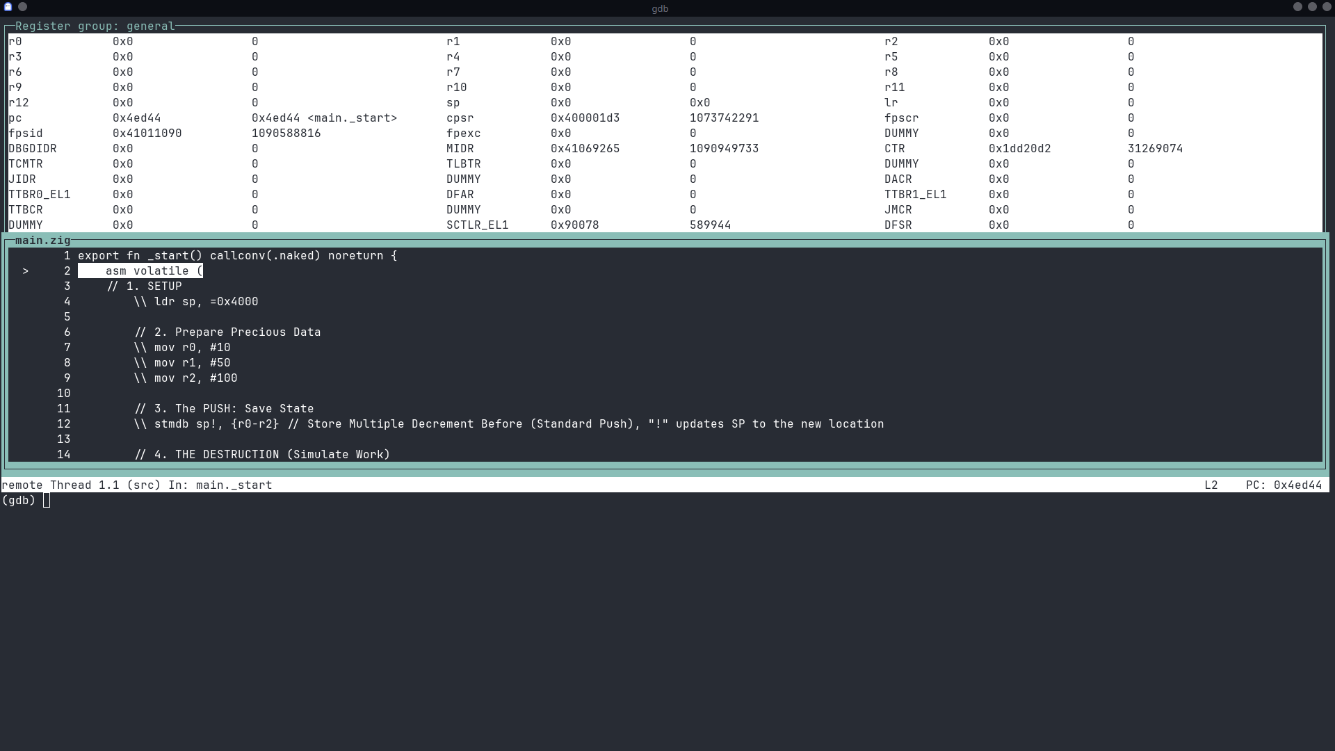
layout reg
You should now see a beautiful text-based UI showing the state of every register in our emulated ARM7TDMI core! It’s our window into the CPU’s soul.
Step-by-Step Execution: Let’s Watch!
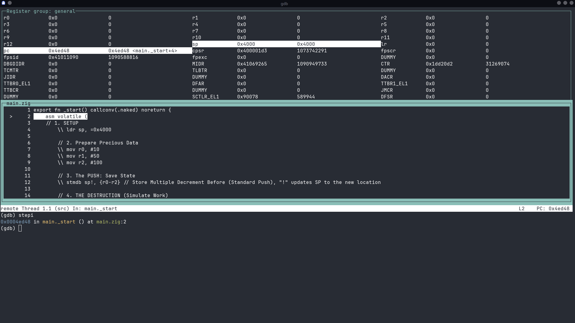
We’re connected! The program is paused right at the first instruction. We’ll use the command stepi (step instruction) to execute one instruction at a time. Run it now to see how the ldr command updates sp.
Step 1: mov r0, #10
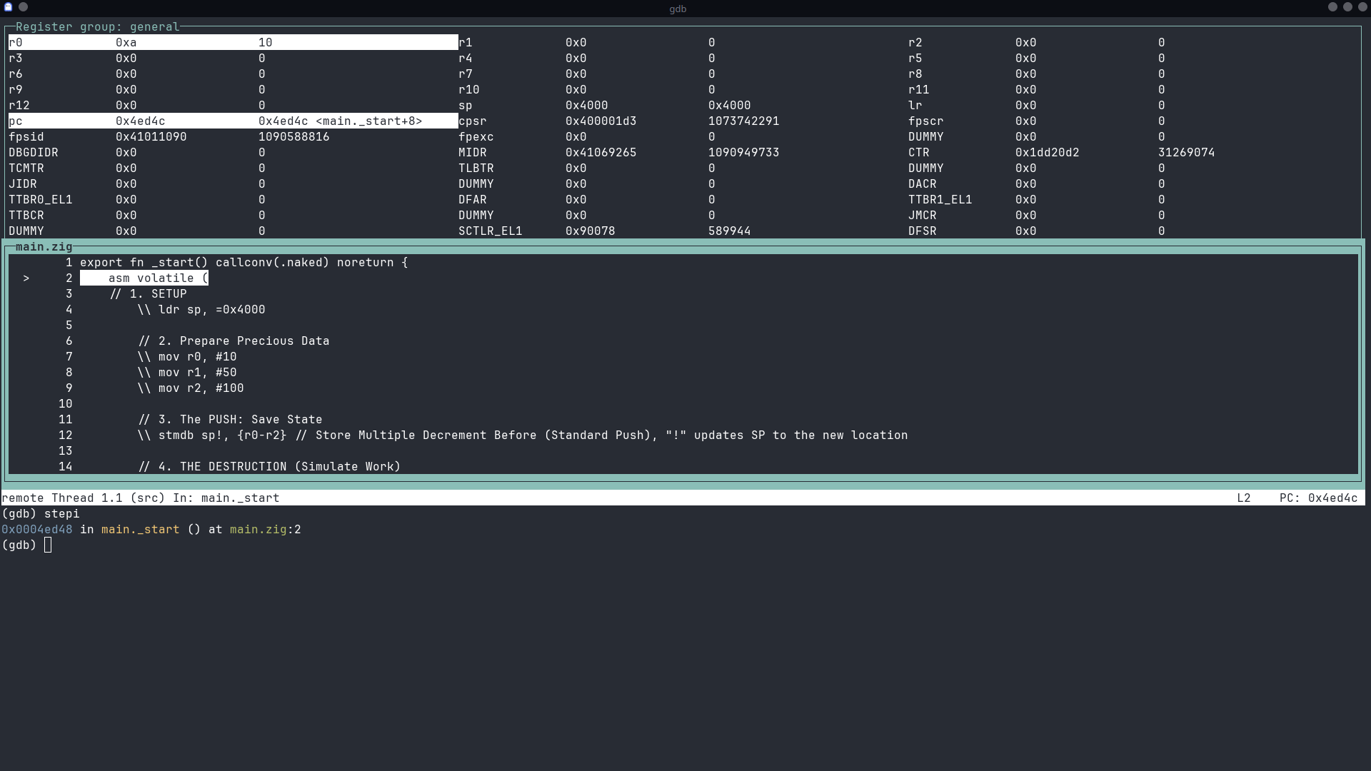
As we covered in our last post, mov is the “move” instruction. It loads an immediate value into a register. Here, we’re putting the number 10 into register r0.
Execute it in GDB:
stepiWhat to look for: The value of r0 in the register layout will change from 0x0 to 0xa (which is 10 in hexadecimal).
Step 2 & 3: mov r1, #50 and mov r2, #100
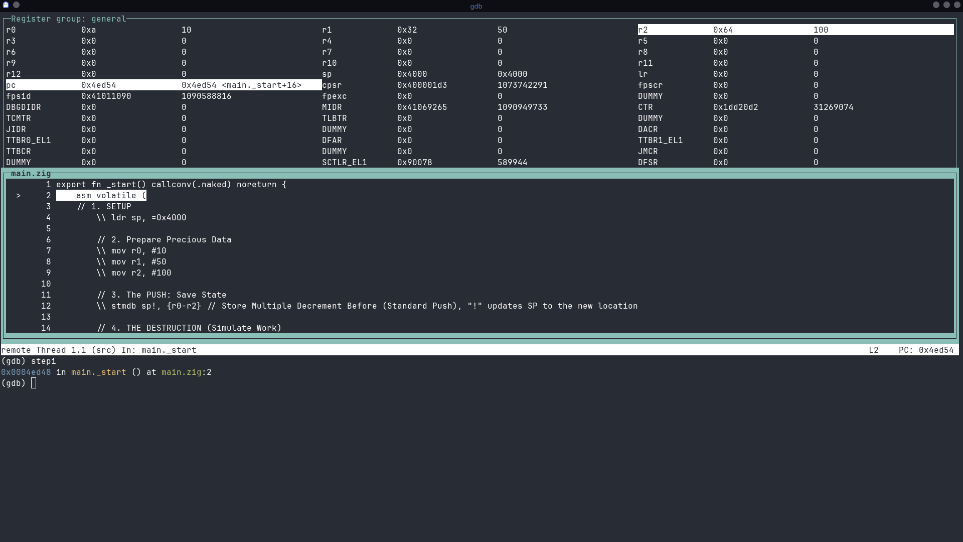
Let’s do the next two together. We’re just loading more values. 50 is 0x32 in hex, and 100 is 0x64.
Execute stepi twice.
What to look for:
r1will become0x32.r2will become0x64.
Our “precious data” is now loaded and ready!
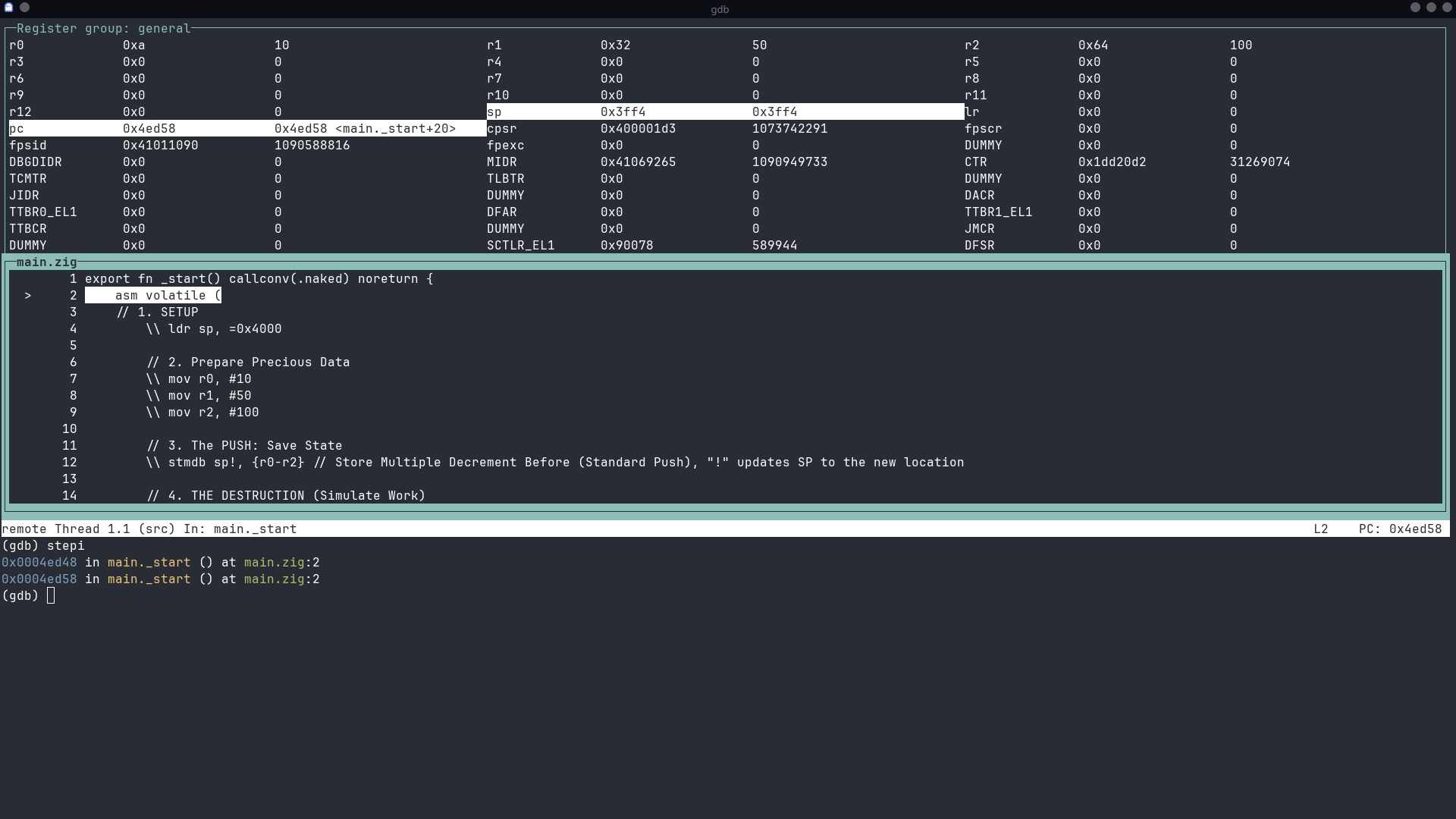
Step 4: stmdb sp!, {r0-r2} - The PUSH
This is a cool one! STMDB stands for STore Multiple Decrement Before. It’s how you “push” multiple registers onto the stack.
sp!: The!means the stack pointer (sp) will be updated after the operation.- Decrement Before: The stack on ARM grows downwards. So, it first decrements the stack pointer to make room, then stores the values.
Execute stepi.
What to look for: The sp register will decrease, and if you were to inspect the memory at that location, you’d see the values 10, 50, and 100 stored safely. This is how functions save their state before running.
Step 5: mov r0, #0, mov r1, #0, mov r2, #0 - The DESTRUCTION!
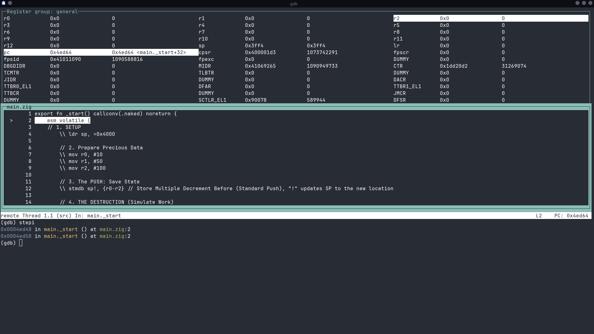
Now we simulate our program doing some work, which clobbers the values in r0, r1, and r2. We’re just setting them all to zero.
Execute stepi three times.
What to look for: r0, r1, and r2 will all be reset to 0x0. Our precious data is gone! …Or is it?
Step 6: ldmia sp!, {r0-r2} - The POP!
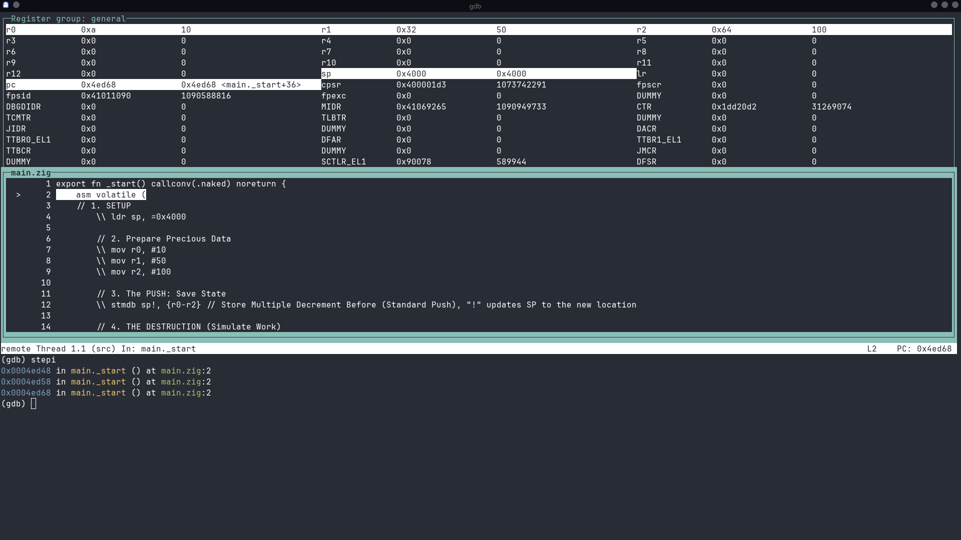
Here comes the hero! LDMIA is LoaD Multiple Increment After. It’s the opposite of our push. It “pops” values off the stack and back into our registers.
Execute stepi.
What to look for: YES! r0, r1, and r2 are magically restored to 0xa (10), 0x32 (50), and 0x64 (100). The stack pointer (sp) also moves back up. Our data is safe!
Conclusion
And there you have it! We’ve successfully walked through a real ARM program, instruction by instruction. You saw registers load with data, you saw that data get saved to the stack, you saw it get “destroyed,” and you saw it get perfectly restored.
This is the fundamental process happening millions of times a second inside your devices. By using tools like GDB and QEMU, we can peel back the layers of abstraction and see the beautiful, logical dance of the CPU right before our eyes.
Happy debugging!